


F16fan
-
Posts
10 -
Joined
-
Last visited
F16fan's Achievements
0
Reputation
-

Low Coolant Light
F16fan replied to pulsarjab's topic in Engine, Transmission, Engine Cooling, & Hydraulics
Ktloah, Holy Crap!!!!!!! After 3 years a solution! You rock!!!!!!! Do you have the part# and cost? How long has it lasted without giving a false reading? Are their tanks metal, and bolt right into original location without modification? Now the question is, is the 97 and 04 Dynasty coolant overflow tanks the same? Is it located in same location? (left side of engine bay) Sorry for all the questions, but this is very important to me and several others! -
Low Coolant Light
F16fan replied to pulsarjab's topic in Engine, Transmission, Engine Cooling, & Hydraulics
John, You are right, the coach had a lot of problems. The repair list started at over 100 issues. It is now down to just 15 items! (Mostly interior) Ray is correct, that is what most of the info online says. Jacwjames, Are you sure? Just when I think I am figuring this stuff out, another curve ball! What direction does your fan spin if you are at back of the HYD fan, looking toward the radiator? Do you have the 1 or 2 fans? Maybe the 02 Windsor is completely different than 97 Dynasty. -
Low Coolant Light
F16fan replied to pulsarjab's topic in Engine, Transmission, Engine Cooling, & Hydraulics
Vito is correct. This is the temporary solution, so many of us have tried. The problem is, if you are disabled, pulling the cooling tank every 6 months to swap out probes, is problematic. Doing the same repair over and over is not a solution. With the metal tank that jackwjames has suggested, if nothing else, it would make it more convenient, if the Ford probes have the same problem, because you would not need to drop the tank to get to the probe. The probe is on the side, so need to drop the tank just to maintain the probe. And if you get in the habit of having the light come on, it renderers the warning system useless! When that light comes on in a properly functioning system, YOU PULL OVER IMMEDITELY!!! If the light comes on, and your first thought is...Well I guess its time to service the probe agian, you may not take it as seriously as you should, and wait for the next time to conveniently check the level, instead over pulling over immediately. Please more experts chime in with your thoughts. Has anyone else switched over to the metal tank and Ford probe? If you have a new Ford probe, how long will it last before, repeating the work around Vito has mentioned? Once I fix it, I don't want to have to any problems for several/many years. -
Low Coolant Light
F16fan replied to pulsarjab's topic in Engine, Transmission, Engine Cooling, & Hydraulics
Since the coolant light was on always since the used coach was purchased, the only way to monitor was to watch the engine temp gauge. On last trip attempt (In the middle of Texas summer), outside air temps were above 100. Since day one, the coach overheated anytime the temps were upper 90's, so I was very nervous and watching the gauge like a hawk.. 15 minutes after departing, the overheating began. Dash temp gauge reached 215ish, so pulled over, and let cool down. Checked coolant, and due to a bad gasket on the coolant overflow, some coolant was present in the engine bay. Topped off. For the next two hours, had to pull over two more times and repeat. Then once I was in the very hilly portion of north Texas, temps started coming up agian. There was no safe place to pull over, so I pressed on cautiously. Then the temp gauge surged to 225, and I was panicking, looking for an exit or anything safe to pull over. Then temp kept climbing, and in an instant, the temp went to zero, smoke started pouring out of the engine bay, lost all power. Coasted into an exit, but the damage was done. All coolant was all over the entire engine compartment, and overflow was bone dry. The result, being stuck for 4 weeks. Found a used engine, and was towed to Cummings in Amarillo for the engine swap. Thought I cracked or warped the head, but turned out it scored all piston sleeves, cracked the exhaust manifold, etc. On way back from engine swap, it all started agian. But outside temps at night came down to middle 80's, and I was able to get back home. Turns out, my cooling stack (Radiator/Tranny cooler, CAC/HYD cooler) was completely clogged. Tried to clean, but it was slid grease and gunk. On removal of the cooling stack, I determined the root cause was the HYD fan motor O-ring failed, and dripped slowly out, over many years and clogged the inside of the radiator. Repaired/replaced everything. In doing so, I determined the Fans Blades were wrong for the direction of rotation!!!!! My fan was trying to blow air to outside of RV! And because the blades were wrong, it really overworked the fan motor. Long story short, over $15K in repairs (And this is cheap, due to used replacement engine, and I performed cooling stack restoration on my own.), just because my low coolant light did not work. So please, some find a permanent solution, before this happens to the next guy. WOW!!!! Thank you for your info jacwjames! I will look into this right now! I did not see the plastic bean shaped Volvo tank with the sensor on side on the link, so I think the 02 Windsor is different than the 97 Dynasty. But all that maters is that the metal tank will directly bolt on, in original location. This is what my stock installation looks like. (See pic).thumb.jpg.05813749f69aa7c01e036eafdfde9e25.jpg)
-
Low Coolant Light
F16fan replied to pulsarjab's topic in Engine, Transmission, Engine Cooling, & Hydraulics
This is a problem on all the older Monaco's. Corrosion builds up over time on the in-tank metal probe. The probe is located on the top of the plastic coolant overflow tank. It will have 1 or two wires going to it. There are YouTube videos of how to clean it, but the problem will keep coming back. My group of Dynasty owners, have been trying to solve this problem for almost three years now. If you go to Monaco's website for parts, you may be still able to get one. (Hit &Miss), but know that there are no aftermarket/OEM updated parts for the 1 wire probe. I bought the Volvo tank latest replacement probe, and it had two wire hookups. THIS WILL NOT WORK, no mater how you try to wire it. It has to match the CLA module installed on your coach. Recently, I blew my engine up, due to not having real time low coolant monitoring. So I am amazed there are no permeant solutions for this problem! Someone even experimented with changing diodes on the CLA circuit board with limited success. But the problem came back after 6 months. So all the old pros here, please chime in with your suggestions. This is the last warning light I have on my dash, I really want it fixed!!! Kysor Coolant Level Alarm 1039-07058-01 Monaco (1).pdf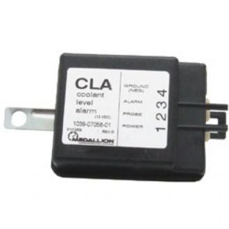

-
just_john1, Fantastic!!!! Well done. We can help so many people by having all the drawings and technical information specific to the 97 Dynasty all in one place. Frank, Awesome!!!!! Together we all can help all the other 97 Monaco Dynasty owners.
-
Here are all the drawings and prints I have for the 97 Monaco Dynasty. If you have any drawings or prints specifically for the 97 Monaco Dynasty, please post them here. 97 Monaco Dynasty Frame Fix.pdf 97 Monaco Dynasty Front & Rear View.pdf 97 Monaco Dynasty GEN Slide HYD RAM.pdf 97 Monaco Dynasty Left Side View.pdf 97 Monaco Dynasty Rear Run Plate Page 2 REV B.pdf 97 Monaco Dynasty Rear Run Plate Page 2.pdf 97 Monaco Dynasty Rear Run Plate REV B.pdf 97 Monaco Dynasty Rear Run Plate.pdf 97 Monaco Dynasty Right Side View REV B.pdf 97 Monaco Dynasty Right Side View.pdf 120 VAC SYSTEM PAGE 2pdf.pdf 120 VAC SYSTEM.pdf 1997 Monaco Dynasty Generator Hydraulic Slide.pdf 1997-2006 Air System Page 1-3.pdf 1997-2006 Air System Page 4-6.pdf Check Engine Lamp & Buzzer.pdf Cum Wtr Pump.pdf Diode Isolator.pdf Engine Elect Panel.pdf Front Air Tank.pdf Frt Tnk Fittings.pdf Kysor Coolant Level Alarm 1039-07058-01 Monaco.pdf Lokar Pedal.pdf Notes 2.pdf Rear Air Tank.pdf Rear Fuse Panel.pdf Rear Run Plate NOTES.pdf RS-4125 Source Engineering drawing.pdf RVA Combined Page 2.pdf RVA Combined.pdf RVA Wiring.pdf Tachometer.pdf Williams Air Throttle.pdf


-
Charge Air Cooler (CAC) & Radiator Removal & Replace (R&R) Instructions for 1997 Monaco Dynasty RV 1) Exterior Cleaning of CAC & Radiator 1. Materials Needed: (1) One (1) Gallon Simple Green Pro (Purple) (2) Sixteen (16) ounces Dawn Ultra Platinum Dish Liquid 2. Tools Required: (1) Foaming Gun Sprayer. (2) Clean 5-gallon bucket. (3) Safety goggles (4) Garden hose attached to nearby water source. 3. Procedure: (1) Mix together Simple Green Pro and Dawn Ultra in clean 5-gallon bucket. (2) Fill foaming spray gun with premixed Simple Green Pro and Dawn Ultra solution. (3) Attach garden hose with water source to foaming spray gun. (4) Spray all CAC/AC Condenser/Oil Cooler/Radiator (Cooling Stack) surfaces, until thick with foam. WARNING: Failure to properly coat the engine side of the radiator (Including the difficult to reach perimeter and corners.) may result in sludge and debris being sprayed from fresh air side of the cooling stack to acuminate and clog the backside of the radiator if the cooling stack is very dirty and/or covered in oil. (5) When under the RV to spray engine side of the radiator, make sure you wear safety googles or even a scuba mask to prevent the degreaser solution from getting into your eyes. (6) Allow to penetrate for 15 minutes. (7) Flush thoroughly until water is clear. (8) Repeat as many times necessary until cooling stack is clean, and water flows clear easily from one side of the cooling stack to the other. (Test spraying from both the fresh air side and engine side.Can also use flashlight at night.) 2) Flush Out Complete Cooling System 1. Materials Needed: (1) Four (4) gallons of PEAK Final Charge 100% Coolant. (2) Six (6) gallons Peak Final Charge 50/50 Coolant (3) Twenty (20) gallons of Distilled Water. (4) Sixty-six ounces of Cooling System Cleaner. (5) Two (2) Cummins thermostats Part Number (PN) XXXXX. (6) Cummins thermostat gasket PN XXXXX. 2. Tools Required: (1) 10 MM socket and socket driver for Lower Radiator hose removal. (2) Seven (7) 5-Gal. buckets with lids. (3) One gallon used milk jugs for coolant recovery/recycling. (4) Very large Drain Pan. (5) Garden hose attached to nearby water source. 3. Procedure: (1) Turn dash heater to full hot for the rest of the procedures—fan off. With the engine cold or at least cool, drain coolant. (2) Open Radiator Drain located at bottom left corner of the radiator. (3) Fill Drain Pan, and close Radiator Drain. (4) Empty Drain Pan into used 1-gallon containers for recycling. (5) Repeat steps (3.2) - (3.4) until coolant system is empty. (6) Refill cooling system with tap water. IMPORTANT: Be sure to remove any air lock from the thermostat housing. Loosen the coolant line to the air pump and bleed the air out. (7) Start engine and allow to warm up (Use the cruise control to select idle speed of 1,000-1,100 rpms). (8) Run for about 10 minutes up to regular temp (180 Degrees). WARNING: If the temp gauge does not rise as normal, you have an air block and need to bleed the thermostat housing again before proceeding. (9) Allow engine to cool 20-30 minutes and drain again. (10)Repeat until the water color is clear. (11)Add a Cooling System Cleaner, following the manufacturer’s directions. (12)Run engine, back up to the normal 180 degrees. (13)Allow engine to cool, drain and repeat flush as many times as necessary until water is clear. Run the engine to 180 degrees at least once with tap water. (14)If your hoses are over 3-4 years old, this is the time to change all hoses in the cooling system and thermostats with new gasket. (15)Last Rinse is with distilled water. WARNING: Do not skip this step and leave the now clean cooling system full of potentially high-mineral content tap water. (There will be several gallons of residual water that you cannot easily remove). (16)Run engine for 10 minutes after getting to 180-degree operating temperature. (17)Cool and drain. 3) Removal of Cooling Stack and Hydraulic Fan Assemby 1. Materials Needed: (1) Spray can of engine cleaner/degreaser. (2) Spray can of penetrating oil. (3) Several unfolded large cardboard boxes. 2. Tools Required: (1) Cordless Drill/Impact Wrench. (2) #2 Phillips bit with 6” bit holder extension. (3) Bore/end scope with flexible Semi-Rigid Cable. (4) 3/8” Socket. (5) ½” Socket. (6) 7/16” Socket. (7) 9/16” Socket. (8) 1 1/8” Socket. (9) Two (2) 1-foot socket wrench extensions. (Min. of 2-feet required.) (10)Ratchetting socket wrench. (11)3/8” Small ratcheting closed end wrench. (12)11/16” Open-end wrench. (13)5/8” Open-end wrench. (14)9/16” Open-end wrench. (15)1 ¼” Open-end wrench. (16)3/16” Alen Wrench. (Or 3/16 Alen Wrench bit socket, with short ratchetting socket wrench.) (17)Large Floor Jack. (18)Minimum 1-foot metal Breaker Bar 3. Procedure: (1) Remove four (4) #2 Philips screws using 6” bit extension and cordless drill from cooling stack ventilated cover on left rear of body. (2) Replace four (4) #2 Phillips screws back into fiberglass of body, after cover removal. (3) Spray penetrating oil on all visible fasteners. Use of the spray engine degreaser may be necessary, if the fasteners to be removed are not visible and covered in grease. There are: (a) Eight (8) 7/16 Bolts holding the AC condenser to cooling stack. (b) Ten (10) 3/8” self-taping screws attaching rubber shroud to cooling stack. (c) Two (2) 1 1/8” nuts holding cooling stack to metal frame. (d) Two (2) 7/16” fasteners on bottom rubber shroud bracket. One (1) bolt & One (1) self-tapping screw. (e) Two (2) 7/16” fasteners on bottom cooling stack mounting bracket. (f) Eight (8) bolts attaching fan assembly to radiator. (g) Two (2) sets of U-Bolts holding lower metal water line, going from water pump to lower radiator hose, and hanging bracket on front CAC 4” air line (toward rear.). (4) Leave penetrating oil on all fasteners overnight. (Re-apply several times if needed.) (5) Remove Eight (8) 7/16” Bolts holding the AC condenser to cooling stack. (6) Lean folded carboard box against coach body in front of cooling stack ventilated cover opening on left rear of body. (7) Pull AC condenser straight out. WARNING: Be care full not to damage or bend fins on AC Condenser. (8) Rest right side of AC condenser on ground, and lean left side against unfolded card board box, so not to scratch coach paint with left side of AC Condenser mounting bracket. (9) WARNING: AC system must be evacuated before proceeding. Use 11/16” and 5/8” Open-end wrenches to loosen and remove top AC hydraulic hose. (10) Use 5/8” and 9/16” Open-end wrenches to loosen and remove bottom AC hydraulic hose. (11)Place AC condenser in safe place, taking care not to damage cooling fins. If required wash back side of the condenser using method, materials and tools described in section 1). (12)Remove five (5) 3/8” self-taping screws holding the rubber cooling stack shroud in place from bottom of cooling stack assembly, using 3/8” socket and cordless drill. NOTE: Middle self-taping screw has two (2) washers on it. (13)Remove two (2) 3/8” fasteners from lower rubber shroud bracket. (One (1) self-taping and one (1) bolt.), using 3/8” socket and cordless drill. NOTE: Direction and placement of bracket. Curved end mounts to fiberglass coach body, and curves up. (14)Remove two (2) 9/16” fasteners from lower main metal shroud bracket. (15)Unfold rubber shroud on top of cooling stack, to gain access to the five (5) rubber shroud self-taping mounting screws. (16)Remove the five (5) 3/8” self-taping screws holding the rubber cooling stack shroud in place on top of cooling stack assembly, using 3/8” Small ratcheting closed end wrench. NOTE: The rubber shroud seam is on top and in middle of the cooling stack. The overlapping portion is on top facing the rear of the coach. (17)Remove two (2) Hydraulic cooling lines from hydraulic cooler using 1 1/4” open end wrench. Use 5-Gal bucket to catch draining fluid. (18)Remove two (2) Transmission cooling lines from Radiator using XX” open end wrench. Use 5-Gal bucket to catch draining fluid. (19)Remove two (2) 4” Air lines form CAC using ½” socket and extension. (20)Remove one (1) large Hydraulic cooling line from hydraulic fan using XX” open end wrench. Use 5-Gal bucket to catch draining fluid. (21)Remove the U-Bolt holding lower metal water line from frame bracket at rear of metal shroud using 9/16” deep socket. (22)Place large floor jack under cooling stack, and jack up until contact with bottom of cooling stack. (23)Remove two (2) large cooling stack mounting bolts, using 1 1/8” Socket, with several extensions with Breaker Bar if necessary. (24)Lower cooling stack slowly using floor jack. WARNING: Be careful not to catch metal shroud on U-Bolt bracket at rear of cooling stack. (25)Angle and roll entire cooling stack assembly on floor jack out from the coach body. System Cleaning Videos: https://youtu.be/ZMm5rmSn4SI https://youtu.be/2tEtXS1MQgM https://youtu.be/HWUIuQMxLTM System Flushing Videos: CAC Body Mod: CAC Removal Prep Videos: CAC Removal Videos: Entire Cooling Stack Removal Videos: Hose Replacement Videos: Hose Re-Assemby Videos: Cooling Fan Re-Assemby Videos: Cooling Stack Re-Assemby Videos: Final Assembly: Cummins Lower Inlet Water Hose Problems: 97 Monaco Dynasty Cooling Stack R&R.pdf

-
Thank you for the correction! Here is the corrected revision: 97 Monaco Dynasty GEN Slide HYD RAM R&R.pdf
-
F16fan changed their profile photo
-
Here is the procedure to remove and replace (R&R) the Generator Slide Hydraulic RAM Cylinder on the 97 Monaco Dynasty. I paid $330 for the 1” X 2” rebuild kit ($30.00) and labor ($300) at Carter Hydraulics in Aledo Tx. Charles had his done for around $250.00 down near Waco TX. a few years ago. I think if you shop around, you can probably get it done for around $300.00. If anyone here has performed a R&R your coach or knows the original Monaco Part Number or the Wen original part number, please make suggestions/corrections to the procedure, and I will update so we can help others in the future. Gen Slide HYD Cylinder Removal & Replace (R&R) Instructions for 1997 Monaco Dynasty RV Removal of Leaking Hydraulic Cylinder Materials Needed: Spray can of penetrating oil. Spray can of engine cleaner/degreaser. Shop Towels. Several unfolded large cardboard boxes. Tools Required: 1 1/8” Combination Wrench. 1 1/8” Deep socket & Socket Wrench. 15 mm Combination Wrench. Large Vice Grip. Clean 5-gallon bucket. Safety googles Procedure: Using RV leveling jacks, Extend Front Jack completely. Access to repair is under the front center of RV. Lay unfolded big boxes under front center of RV. Crawl under RV and Spray penetrating oil on the two 1 1/8” nuts and threads on both ends of the HYD Cylinder. Use of the spray engine degreaser may be necessary, if the fasteners to be removed are not visible and covered in grease. There are: Four (4) 1 1/8” Nuts holding the HYD Cylinder onto the frame/slide. Allow at least 20 minutes to soak in. Place 5-gallon bucket under Front HYD line, and remove line with 15 mm Combination Wrench. Drain fluid into 5-gallon bucket, and clean end with shop towels, and move pointing up, away from HYD Cylinder. Move 5-gallon bucket under Rear HYD line, and remove line with 15 mm Combination Wrench. Drain fluid into 5-gallon bucket, and clean end with shop towels, and move pointing up, away from HYD Cylinder. Use 1 1/8” Deep socket & Socket Wrench, and remove nut on HYD Cylinder mount bolt facing rear of coach. Place Large Vice Grip on the front threaded area of HYD Cylinder. WARNING: Place Large Vice Grip, away from front two (2) Jam nuts, or damaged threads will not allow for losing nuts. Use 1 1/8” Combination Wrench to remove front nut, while holding Vice Grip, so the HYD Ram will not rotate. Leave the two (2) Jam nuts in place. Push GEN Slide out slightly, until HYD Ram is free from mounting bracket. The HYD Cylinder front Ram can now rest on metal cross brace. Remove HYD Cylinder by moving forward, so that rear bolt mount clears mounting bracket, and place on ground. Now move rearward and lower front Ram to ground. Replacing Re-Built Hydraulic Cylinder Materials Needed: Shop Towels. Dexron VI Automatic Transmission Fluid Tools Required: 1 1/8” Combination Wrench. 1 1/8” Deep socket & Socket Wrench. 15 mm Combination Wrench. Large Vice Grip. Safety googles Funnel with very long Flexible neck. Procedure: Place Repaired HYD Cylinder on ground, under center front of RV. Lift Front of Ram up, and place on metal cross support. Lift Rear of Cylinder up, and insert threaded mount bolt through rear mounting bracket. Install and tighten rear nut, with 1 1/8” Deep socket & Socket Wrench. Move GEN Slide forward, and lift Front Ram thread mount into bracket. Place Large Vice Grip on the front threaded area of HYD Cylinder. Warning: place Large Vice Grip, away from front two (2) Jam nuts, or damaged threads will not allow for losing nuts. Install and tighten Front nut, with 1 1/8” Combination Wrench, while holding Vice Grip, so the HYD Ram will not rotate. NOTE: When front of threaded Ram bolt makes contact with front of bracket, it is in proper position. No Adjustment of Jam Nuts is necessary. Re-attach Front HYD line with 15 mm Combination Wrench. Re-attach Rear HYD line with 15 mm Combination Wrench. Raise front RV leveling jack, leave down 6” from full retract, and leave system on. Fill front HYD tank with Dexron VI Automatic Transmission Fluid using Funnel with very long Flexible neck, following instructions from RV Owner’s Manual: Unscrew the reservoir cap located on the pump. Fill the reservoir with fluid until the warning bell goes off. Replace the reservoir cap. Now fully retract front leveling jack. Run GEN Slide in and out several times. NOTE: To avoid damage to GEN Slide HYD Pump, wait several minutes between sliding out GEN Slide fully, and retracting fully. Repeat if necessary, until GEN Slide moves smoothly in and out. Videos: 1997 Monaco Dynasty Gen Slide HYD RAM R&R.pdf 97 Monaco Dynasty GEN Slide HYD RAM.pdf 1997 Monaco Dynasty Generator Hydraulic Slide.pdf


.jpg.094149b6662c26d01b1dce4802bc64a2.jpg)


