


StellaTariche
-
Posts
95 -
Joined
-
Last visited
-
Days Won
7
Content Type
Forums
Downloads
Articles
Gallery
Blogs
Events
Store
Posts posted by StellaTariche
-
-
Hi David,
Good idea, but since I'm not the original author, I can't delete or edit it.
I did send a private message to the original author (Joe) about deleting it or changing it.
Thanks for the suggestion.
- John
-
"Wow they have so many pan tilt cameras, which one goes with the 360 system?"
Bill,
The pan / tilt camera is separate and unrelated from the 360 camera system.
I just mounted the pan / tilt on the roof, use POE to power it, drop it down through the same hole, and use a phone app (or HDMI switcher) to see what I'm about to hit.
"Hit things, John Does"
- Master YodaAn HDMI camera switching system is a nice addition when you have a lot of cameras you want to switch between.
-
 1
1
-
-
29 minutes ago, Corkman said:
It's Bill again. I plan to order this, but it seems like there are 2 different size camera, is that correct?
Also, what size monitor did you get, 7 inch or 10 inch?
Hi Bill,
- Get the small cameras
- Get the 10" monitor (the 7" is too small for my eyes, especially if you are showing the split screen view)
- Also, remember to order the "RV" model: Longer camera wires, and you can choose the "vehicle" image, which can be stretched to accurately show your coach. You can also choose a "Class C" image, a "School Bus" Image and several others.
I was gonna use a 1966 Batmobile image (special order to make a custom image), as I used to own a street legal 1966 batmobile:

Here is the contact information for SZDALOS. They usually respond in one day (time zone stuff):
Shenzhen dalos electronics co., limited
Contact person: Dories Liu
www.szdalos.cn
Email: info@szdalos.com
Skype: doris-hid
Wechat/whatsapp: +86-18682022573
Tel: +86-13691627132 -
BTW, if you are good with fiberglass and dash mods, THIS is an option I also considered,making an enclosure and placing it closer to the windshield (below the high hump the gauges are in)
https://www.amazon.com/Blackmagic-Design-Smartview-Rackmountable-Monitors/dp/B005CSLWGG
(I was worried about glare, so I went with the single 10” monitor.)

-
Hi Bill.
You only see the flattened and stitched together images - just like a drone would see.
You *can* choose to see two different flattened and stitched images side by side (selectable) or only a single image.
You can also see the unprocessed fish eye camera outputs (if you like) (not sure why anyone would).
AND for integrity, the four separate camera outputs - unprocessed- are actually what is recorded. Insurance and police want to see the unprocessed originals if there is a need. They have tools to stitch them together if needed.
BTW, a separate weather proof camera that has pan an tilt controls- controlled by your iPhone /iPad - mounted on the roof - is a great way to see that low hanging tree branch. Inexpensive. Get the night vision version. About $80.
- John
22 hours ago, dl_racing427 said:I'm amazed that you accomplished all this for only $30K.
Slave labor is awesome 🙂
-
 1
1
-
-
(Dwight asked me “How to install the 360 degree bird’s eye view camera system”)
So here it is, in detail, with links to the inexpensive “extras” you’ll need to purchase.
Lots of “tricks” i learned too. Hope it helps.- John
_____________
Hi Dwight.
Running the wires is easy - as long as you don't mind them being on the roof. Any other way would be brutal unless you have hollow outside walls (you don’t) 🙂
As I already have a ton of solar panels (with wires), running four more cables wasn't a big deal.
All of the cameras are tiny (less than a 3/4" cube). The connectors are "BMW" style, which means they are color coded, skinny, indexed, with 4 internal conductors - about the diameter of the wire itself (3/16"). The cameras get power through the cables. You can paint the camera to match your coach (mask off the lens).
First things first:
- Amazon sells rolls of expandable wire sleeving (search for “UV expandable wire sleeving"). You are going to need a lot of it. I used the white UV kind to match the roof.
- The sleeves work like those Chinese finger traps. Push to open it, slide the wire in, pull to take out the slack. These protect (and bundle) the camera cables. Not expensive.
- Three individual camera wires (rear, and side x 2) will be covered in the wire sleeves all the way from the cameras to the main entry by the front end cap.
- You'll need another larger diameter roll of UV expandable wire sleeving to bundle the three camera wires (rear, and side x 2) to go from midway to the front cap. Same procedure, just with three previously sleeved cables.
- Insulate the section of wire in the fridge chimney. you can wrap the small two foot section in the fridge chimney cable in one layer, then use metal tape to wrap that, then another layer. Or find some insulated sleeving (I had some of the insulated tape)
- To secure the wires to the roof, I used these things: https://www.amazon.com/Adhesive-Backed-100-Pack-Nova-White/dp/B072R6GFKW Buy a big bag. You'll need to secure the wire about every 12" up there.
- Clean the roof with acetone where these will be stuck just before sticking them down.
- Buy a big bag of 4” UV resistant wire ties (white). They go through the cable tie bases. Use two cable ties per mount - criss-cross them. Clip off the excess.
- Lastly, buy a bunch of self leveling sealant for RV roofs. You'll use it to seal the cables to the tie bases, and seal the tie base edges to the roof.
NOTE: The camera wires WILL whistle and rattle and drive you crazy if the cable mounts are too far apart. 12” spacing seems to work best.
Then, You'll need one of these Winegard Roof Cable Entry Plates: https://www.amazon.com/Winegard-CE4000-Cable-Entry-Plate/dp/B009LX1JWU to get the wires through the roof into your front cabinet area.
Mounting the cameras:
- Mount the cameras up high. Make sure each camera can see the bumper (front or rear) or the RV side all the way to the ground.
- Throw away the cheap #4 screws that came with the unit, and get some good stainless #6 cap screws (allen / hex / or square drive holes). They will not strip. Fiberglass is hard to screw into, and will break off a screw. Drill the holes only slightly smaller than needed, unless you like broken screw removal.
- Rear Camera: Make sure the camera can see the rear bumper. My rear camera sits right next to the existing rear view camera. Drill a hole through the end cap, slide the wire through. Fish it out on the top of the end cap (mine has a big air intake, so that was easy). Run the wire to the top of the front end cap (all the wires will end up there). Seal up all the holes with clear silicone.
- Front camera is easy too: Mount it above the windshield. Make sure the camera can see the front bumper. Drill a hole to pass the wire through. (don't forget to silicone the holes when done).
- DON'T ACCIDENTALLY DRILL THROUGH YOUR WINDSHIELD, RIGHT?
- Driver Side Camera: Trickier on the slide side of mine (only one big wall slide on driver side), but same idea:
- The side camera has to mount on the slide wall, and the slide wall moves. So, I put a 2" square of awning tape on both sides of the slide topper awning, put a brass grommet right through the tape, about 1" from the roof, sealed the grommet with superglue so the awning material won't unravel. Then you slip the camera in from the underside of the grommet/awning, through the grommet, and on to the roof. If the wire sleeve isn't the right color to match your roof, and you care, wrap it in UV resistant colored electrical tape. You'll never see it.
- Mounted the side camera on the slide wall. Make sure the camera can see the side of the coach at a the bottom.
- LEAVE enough slack under the awning for the slide to go out. Silicone the grommet so no water can get on the slide and so the cable won't slip.
- Run the first side camera wire to the center to meet the rear and other side wire.
- Bundle all three cables together where the meet midway on the roof to the front cap using the larger diameter expandable wire sleeving. Run all three bundled cables to the front cap area.
- If you can mount the cameras between the passenger slides (has to be more or less in the center of the coach), AND you can avoid the big awning, great!
- If not - I could not - my passenger side camera is about 10" down the wall and underneath metal covered awning protector)... so...
- Drill a hole in side wall at the fridge chimney area about 10” down the coach wall. Slip the side camera cable through the hole in the side wall. Cover the chimney wire section with heat resistant insulation (Home Depot). Come out the fridge chimney, run the wire to the center to meet the others.
- IMPORTANT TO REPEAT: Insulate the wire in the chimney vent.
- Now, with all three camera wires up front, Find a spot to get the three wires through the roof and into either the front cap space, or inside any front cabinet area you may have.
- Use the Winegard cable entry plate to go through the roof (Amazon link above). I had a hole where I took off my old Dish antenna, and used that.
- Seal the cable entry plate top and bottom with self leveling sealant. Make sure the wires don't rub on bare metal.
Getting the wires to the camera splicing computer
- All the camera wires wires plug into the splicing computer harness. The harness plugs into the splicing computer (about the size of a thick iPhone in a case).
- You want to mount the computer under the dash with easy access, because you'll need power, ground, access to the reverse and turn signal wires, and access to the monitor wire.
- Note, you can run it without connecting to the reverse and turn signal wires. It's just nicer when using them (the camera angles change to "see around" corners and show the back of the coach better in reverse). I already have a really good dedicated reverse camera, so I only connected the turn signal wires.
Access to the monitor.
- At first, I used my in-dash radio as a monitor. meh.
- BUT, I really, REALLY like having it on the dash. If you line it up right, it is just like a flight simulator. You are seated up high, and it doesn't block my view at all.
- I purchased a 10" monitor that SZDALOS sells (see the photo in the thread) and painted it to match my other toys and dash, but you could tie it into any monitor you like (and that you can see while driving).
- The SZDALOS Monitor has composite, VGA and HDMI inputs. You can use all three (switchable) and connect another camera or three (switch between backup camera, rear bedroom camera, camera aimed at you engine, etc. The monitor has a small remote to switch inputs, adjust brightness, etc. Less than $100. Good quality.
- The splicing computer supports several video outputs: VGA DB-9 connector, composite video (yellow RCA-type) and HDMI, BUT ONLY ONE OUTPUT AT A TIME.
- Helpful Dash Modification: I made a special connector out of a 1.5" plastic desk wire hole cover that fits a hole I drilled in my dash (you can’t even see it), and mounted an double sided HDMI socket and matching power socket in the plastic connector thingy (apologies - electrical engineer geek). Using a small special 3" HDMI cable (they exist!) and a small 3" power cable, I can quick disconnect the monitor if not needed. Monitor fits in the cabinet above.
- Attaching the monitor to the dash: I super-glued a bunch of strong magnets to the monitor base plate, and ALSO to the underside of the dash (after finding the sweet spot for driving). Works great. Used 14 magnets (7 on top, 7 under the dash). It ain't going anywhere unless I want it to. Link to the magnets: https://www.amazon.com/dp/B089CZG942
- If you want the cameras to go to multiple monitors in the coach: I ran the HDMI output from the splicing computer into an 1x2 HDMI splitter, then one HDMI into my Onkyo receiver, one into the dash monitor. Since I already have a long HDMI run between the front Onkyo (dual HDMI outputs) and the bedroom Onkyo receiver, that's how I connected the who she-bang to the rear bedroom TV. I ran the long HDMI cable (get a really good one with thick gauge internal wires, cause it's 40 ft.) in the air ducts to get to the bedroom.
-
Running a thick HDMI cable from dash to the back bedroom was a pain in the arse. While I was doing that, I also ran two CAT-6 ethernet wires (use “plenum rated” cables) from the front to the back bedroom. There is a wireless access point and an 8 port POE switch in both the front and back of the coach. The POE (Power Over Ethernet) switch makes powering any other cameras easy (I have one installed in the engine bay to keep an eye on things, and one in the bedroom/storage area to see what went “crash” when driving. Stuff happens.
Surely I will die of Wi-Fi radiation poisoning from all this 🙂 - You could also use an HDMI wireless transmitter to get to the back bedroom TV. That would have been easier.
Connecting it all together:
- Finally, route all four camera wires down the A-pillar - I used the driver’s side pillar, then under the dash. Getting A-Pillar on and off can be a PITA, but mine went ok.
- Switched Power: I used an existing dash switch ("radio") to power the dash monitor because sometimes I want to leave the camera system running / recording with the monitor(s) off.
- The camera system will record to a 64GB memory card or 64GB thumb drive. Good for security, or if involved in an accident - insurance proof that someone hit you. The camera system recording function can be turned on or off. Mines stays on all the time recording - even when in storage. It uses about 40 watts at 12V, so almost nothing.
- Make sure you can get to the computer to retrieve the memory card or thumb drive in an emergency.
- I also have the ability to monitor my coach over the internet. So I want the ability to independently power the monitors, and camera system. When stored a few miles from my home, I can log in to a wi-fi box in the coach that will show me inside cameras, the 360 outside cameras feed, battery levels, temperature, etc. Way Cool.
Adjusting the cameras:
- SZDALOS send you with a big roll of specially marked tape. You are supposed to stick it to the ground at specific intervals, turn on the system, then "splice" the individual camera images together by looking at the camera images through the monitor. I didn’t use the tape.
- The splicing process took me about 45 minutes after all the measurements are laid out on the ground.
- Backup your splice settings (it is a menu choice), shut the system down, pull out the memory card, save them to a real computer, then put the memory card back in the splicing computer. That way, if the computer goes bad (my first one did), they'll send you a replacement - and you just restore your settings.
- Then you are done. Ta-DA!
Splicing the camera - tricks:
- An empty parking lot with straight lines is your friend.
- The tape did not stick to the asphalt and blew away in windy Colorado Springs. Lots of bad words.
- Instead, I used kids sidewalk chalk. Get different colors. BRIGHT colors, not that Easter Egg looking pastel stuff.
- The measuring and layout takes longer than the actual convergence splicing.The splicing took me about 45 minutes. Measuring properly (the second time, right) took me two hours. Never time time to measure properly, always time to do it again 😞
- Some of the "splicing” involve merging points that are about 3 ft off the ground (the directions make it clear where and how).
- SZDALOS says to stack the boxes that the units ship in to get the right height. NOPE.
- Instead, I used a microphone stand (and also a camera tripod) with colorful tape at the correct height.
- The hardest splice points to see are in the far corners (these are fish eye lenses, and work great). COLORFUL chalk or COLORFUL duck tape make it easier.
- I went to Harbor Freight and got a "rolling measuring wheel". Save yourself hours and spend the $9 for the rolling measuring wheel. Link: https://www.harborfreight.com/1000-ft-measuring-wheel-95701.html
- Keep your lines parallel and straight. It matters.
- When washing your rig, clean the camera lenses.
- Dont accidentally hit the cameras and knock them out of alignment. You will probably have to re-do the splicing dance. You will be pissed.
Attached is a layout SZDALOS sent me for a 40' RV (this is what you must tape/draw on the ground to "splice" the four cameras together):

Feel free to call or email me directly. John at Lead Free Design dot com (719) 359-5170 direct line.
I’m CEO of my engineering firm, so if I’m in the lab, just leave a message. I return calls,
Best,
- John


-
 2
2
-
lotsa new combination cuss words were exchanged with the boys (men?) in that 70 ft paint booth over those two months.
Also, they learned that the words "automotive" painting should really be "mostly sanding"
- John
-
1
-
1
-
1
-
-
- Popular Post
- Popular Post
Hi All,
Since I'm always asking for assistance (usually with my stupid steering and tail-wagging-the-dog stuff), I though I'd give back a bit.
If anyone would like to know how I did these upgrades, or where to source any of the items, I'd be happy to help.
Thanks to all,
- John
---------------
My 2000 Monaco DIplomat was great - just dated ("pre-ugly") so here's what we did (total upgrades were about $30k):
Upgrades:
- New custom RV Paint (done by me and my three college boys in a rented paint booth). My oldest did the artwork. Looks sorta like "Sonic The Hedge Hog" I think.
- New leather furniture (seats, sofa, dinette cushions, extra trim leather, reading chair). Drop shipped to my engineering lab dock from Los Angeles.
- New toys and stuff (TVs, Stereos, Internet, dash electronics, dash veneer, cameras, awnings, Inverters, Lithium battery banks - 1000ah, 1000w of solar, recirculating water filtration system - filters AND sterilizes your fresh water tank continuously, bidet (really), lighting.
- Replaced the fridge guts with an Amish unit (this was before I put the lithium batteries in) so now it won't burn to the ground. Also, I liked the original cabinetry.
- New floor (Pergo) up front, and new carpet in the bedroom
- LEDs everywhere. New ceiling fixtures. All controlled on remotes or iPhones / iPads
- Almost everything is also voice activated ("Hey Siri")
Dash Specifics:
- I had a 18 year old cracking plastic dash like many of us, complete with B/W CRT backup monitor.
- removed it, fixed the cracks, and used a really nice wood veneer (Bear Claw Oak) to recover the whole thing (and matching side panel).
- used contact cement, and when dry, used a trim router with a small bearing to follow the existing gauge holes.
- removed the original radio and backup CRT, filled the original holes, and cut new ones with a router template I made.
- The radio screen (capacitive touch screen, very few knobs) is now flush and looks like a custom install. The radio has a backup camera input. New high def backup camera, reused the original wires, but soldered on new connectors.
- The original backup CRT replaced with an iPad mini for GPS. Hidden magnets (strong magnets) behind dash to hold in place.
- There is another magnetic mount for my iPhone (music --> apple TV (airplay sounds much better than bluetooth) --> big home Onkyo receiver overhead where the original head banger TV was.
- 46" TV latches safely to the ceiling, drops down for viewing. Painted the back to match the ceiling when in the up position.
- iPad (GPS, Waze) and iPhone (Music, phone calls) are controlled by two bluetooth buttons that I stuck to the "not-smart" wheel. Works perfectly.
- I use Apple's new AirPod Pro ear buds to make/receive calls while driving. They are noise cancelling (but you can still hear warning beeps - it just cuts out the road drone and genset noise). Also used to call the Fetching Mrs Taylor if she is in the back bedroom. All hands free.
Everything is controlled by voice ("Hey Siri, skip this song". "Hey Siri, call my Mom". "Hey Siri, where is the closest Chik-Fil-A"), so hands stay on the wheel.
- Any iPads and iPhones can also control the TV, Amazon Box, Roku Box, Apple TV, Blu-Ray player with one simple app. Wireless and wired charging stations all over the coach. Lights are all on programmable Logitech remotes and iPhones / iPads.
BUT the best improvement was the 360 degree overhead camera system.
- Four cameras (wires run on the roof - can't even see them, and protected by UV sleeves), images stitched together by a computer. Looks like a drone is 50 ft above you. Think "Tesla" dashboard.
- Now, you can see if you are in your lane, if you'll clear that curb, where all the other cars and trucks are. Absolutely game changing.
- A 10" HDMI monitor sits on the dash, directly in line with YOUR lane on the the road. It does NOT block your view at that angle, is attached with magnets hidden under the dash. It is like driving a video game or a flight simulator. The monitor can be left up, or put in a cabinet in 30 seconds.
- The four cameras are all HD, with night vision. You can literally drive with the headlights off and see everything (ever pull in late to a campground?). You can park within 2" of a curb or another obstacle and clearly see what you are doing.
Bonus - Security:
- The output of the 360 camera also feeds into my front main and rear bedroom TV on an HDMI input.
- Want to see what that noise outside is? One button on the TV and now you see everything for 80' in every direction.
- In complete darkness!
I got the camera system on Alibaba from a company SZDALOS.
- Good email support.
- Setup involves marking the ground with playground chalk at specified distances, and lining up on-screen reticles. Not difficult.
- Two weekend days to install, or a car stereo shop can do it for you. Not difficult.
- https://www.alibaba.com/product-detail/SZDALOS-HD-3D-360-Surround-View_62000211116.html
Here is a video of the system in use (click on the video). It really looks just like this, but on your dash. When you use your turn signal (or back up) the cameras "shift" in the direction you want to go. Simply Amazing for less than $500.
Well worth the upgrades, and nothing crazy super expensive.
Makes your 2000 Diplomat ($29K from my dentist in 2014 with 29K miles) look like a 2019 for less than $30k in upgrades:
- the cost of new leather furniture
- a few TVs
- some simple woodworking
- cameras
- two home stereos (2 x Onkyo 7 channel surround receivers
- two hidden subwoofers
- Lithium battery bank
- New Hybrid Inverter
- Solar panels ("peel and stick - really") and solar inverter
- Oh, and my three college kids learned how to prep a coach for automotive painting.
- I learned how to paint and color sand 1100 sq ft of RV surface 😞
- But it looks like a $30k paint job when done.
Lotsa photos. Thanks for all the help over the past few years.
- John
John Taylor
Colorado Springs, Colorado
2000 Monaco Diplomat aka "Uberbounder"---------------------
Final "Uberbounder:
1000w of solar on roof


Complete darkness at a truck stop:

Bidet (really):


TV in down position:

New leather fold out bed (with cool removable tray tables):

- 1000Ah+ of LiFePO4 (Lithium) batteries = same capacity of 16 golf cart batteries. Fully charged in 1.5 hours
- I can run a single roof air (15K BTU) for 8 hours off the battery bank.
- Batteries fit under the bed. (8" x 10" x 48" space)

My reflection in the new paint after color sanding:

The prep and painting crew (college was out for the summer):

New inside (wall slide is in):

The Fetching Mrs. Taylor and Charlie the 90 lb Golden Doodle:


-
11
-
3
-
Hi all,
I did some research with TRW about the "lock the inner and outer shaft" either with a larger pin or spot weld.
Unfortunately, this turns out to be a VERY BAD IDEA.
(Original Post)
On 8/27/2020 at 11:53 PM, highsierra37@att.net said:Another thing to check is the input shaft of the trw steering gear box. The input shaft has a small center shaft and a larger outer shaft that has the splines where the steering shaft connects . The center shaft and outer shaft are separate pieces that are connected together with a pin. I had a recent experience where i found the play in the steering wheel was being caused by movement between the outer an inner shafts on the steering gear box input shaft.
To check for this remove the steering shaft from the steering gear box so you can inspect the input shaft on the steering gear box. Draw a line across the top of the shaft - then use vice grip pliers to slightly rotate the shaft back and forth . The two shafts should be tightly locked together with absolutely no play at all. Just a very small amount of play between these two shafts can give an undesirable amount of play at the rim of the steering wheel .
If play is found between the two shafts an oversize pin can be installed or you might consider a very small spot of weld to permanently lock the shafts together.
Again, unfortunately, this turns out to be a VERY BAD IDEA.
Here is a summary from TRW:
QuoteDo not do what that forum said with the pin. That pin is designed to flex like that. That is one area where you want play.
That is the torsion bar. It works kind of like a torque wrench when it hits a certain torque it kind of flexes like a torque wrench. By messing with that pin or welding it you are eliminating that designed flex. That flex helps open and close a valve that gives you your power steering.
- By messing with it You could cause the steering gear to have intermittent power loss(no power steering).
- It could cause the pin to snap completely and you could lose your ability to turn completely.
- You could over torque the wheel damaging the pump or gearbox significantly by having it locked in place.
So if you see a little bit of play there, that is ok - it’s just doing what it was designed to do. It needs to flex to do what it is designed to do.
Here is a technical description of how the TRW steering box works internally:

tl;dr SUMMARY: DON'T mess with the pin (torsion bar) or BAD THINGS MIGHT HAPPEN.
Hope that helps.
- John
-
1
-
UPDATED WITH SOME NEW SAFETY INFORMATION IN RED (BELOW)
Hi Joe,
I am having the same problem with rotational lash (just posted a question about it to the group). I was told it could be the "intermediate shaft" - again, have not climbed under to see if that exists and might be the problem. I have a properly adjusted TRW steering box (TAS 65). Still have about 1" of play at the steering wheel.
BUT, your problem and solution look interesting...
Couple of questions about the inner / outer shaft fix: (I'm not under the rig - cause #%#$@* cold)
- Removing the steering shaft from the steering box: any tricks I should know?
- How does said "pin" best come out? (will it be obvious, or something else tricky)
- Which shaft should I be rotating with the vice grips (inner/outer)?
- My welding skills need work. Replacing with a slightly larger pin seems like a good idea. Will that also be obvious how to accomplish with the steering box in the rig, or must the steering box come out to have it machined?
Unfortunately according to TRW steering box experts, this is a VERY BAD AND POTENTIALLY DANGEROUS FIX.
I wrote another post with a summary of why...Please read!
Thanks for the help.
- John
John Taylor
Colorado Springs, Colorado
2000 Monaco Diplomat 38, one big wall slide -
Hi all,
I'm chasing down some steering lash in my 2000 Diplomat (38' One big wall slide), and looking for some expertise. 60k miles on the rig. Way too much rotational lash (play) in the steering.
I have a TRW box (TAS 65), and have been getting generous help from Brent at Weller on adjusting it.
Even after the correct adjustment, there is about 1" of play (lash) at the steering wheel.
Pat Gaukel at Douglas Tek (Steering Column Engineering Manager) says the columns themselves are usually NOT the cause of the lash.
I suspect the u-joints (or maybe even the slip joint) might be worn from trying to turn the steering wheel with the engine off, or something related.
Instead (Pat writes): "If the lash is not felt in the column (note: it isn't - John), there is a possibility it could be in the Intermediate shaft. Within the Intermediate shaft there are 2 universal joints and a slip joint - one u-joint at the bottom of the column and the second attaching to the top of the steering gear. Depending upon who made the shaft, the universal joints might be serviceable. If the shaft is made by Dana, they offer a service kit. Some of the others have the bearings staked in place and can’t be serviced, only replaced."
Anyone have any experience with this item, where I might find a new one, the vendor, tricks on replacing it, etc?
After this I'm on to installing the Monaco Watts system. Tired of being blown around I-25.
Thanks,
- John
John Taylor
Colorado Springs, Colorado
2000 Diplomat (38' One big wall slide)
2014 Jeep Cherokee toad -
Here is the Carefree of Colorado version (about $50):
https://www.carefreeofcolorado.com/catalog/part-detail.html?id=15476&bc=0,3,&q=2&pp=24&sst=
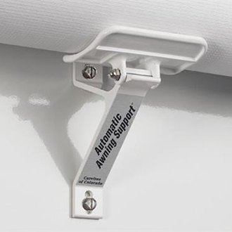
Answered my own question “...does this exist...”
Has anyone used this kind of support before?
Thanks,
- John
=======
UPDATE:
This is the one I purchased:
https://www.dyersonline.com/dometic-black-awning-automatic-cradle-support.html

-
Hi All,
I converted my 20' Carefree to electric a few years back. Works well.
BUT, it sure does sag when I hit a bump. 😞
Having had one of the smaller carefree awnings (back bedroom window) break loose, is a additional center support on a 20' Carefree awning a good idea?
If so, does anyone know where to get such a support?
I assume it would be a fixed bracket, with the almost-completely-rolled-up awning "rolling" onto the support, right?
Thanks again,
- John
-
Hi All,
Update: Finally got another set of hands on the TRW steering box tools, and re-adjusted after centering first.
I also had a shop check the drag link (ok), tie rods (ok), king pins (ok).
The adjustment on the TRW is now tight, perhaps a little too much, but workable. More input is needed, but there is definitely less lash. BUT...
Problem: I still have lash from the wheel to the input of the TRW box. After removing the plastic steering column shroud (so I could see the top of the TWR input shaft), the steering wheel still move about 1". The pitman arm does not move at all when moving the steering wheel to check lash. It looks like it is either (1) the very last universal steering column joint, or (2) the input shaft to the TRW box.
Which mean, I still end up constantly correcting the steering while driving, as the wheels guide themselves due to the lash.
- Is this as good as it will get?
- Is there a way to tell if it is the last universal joint on the column?
- Will a new (reman?) TRW box fix the problem?
Any ideas greatly appreciated.
Thanks again,
- John

-
Mobley Modifications:
The other thing you can do to a Mobley is add an external antenna - on the roof is best. It brings in the outside signal into the coach. Inside the Mobley is a small connector we use for FCC testing. It is normally not used for deployment, but works quite well as an external antenna with the correct adapter.
The modification is not hard:
- Open the Mobley case. Note the location of the internal antenna connection (there are two; only one works - see photo).
- Drill a small hole in the Mobley case (in the right spot)
- Use an antenna adapter to connect to the internal test (see link and photos below)
- Run an external roof antenna cable (through the roof) and connect to the antenna adapter.
You will often increase your cellular signal strength by 10db because of the new antenna, and the location of the new antenna. In addition your Wi-Fi both inside and outside the coach will be significantly improved.
Parts:
(1) Antenna adapter:
Search the link below. You'll want the longer 20.4mm MS156 connector paired with the appropriate SMA connector to match your external antenna:
(2) Cellular, Wi-Fi, and GPS Roof Antenna:
Here's what I have. It has 4 antennas inside. Low profile - about the size of a baseball cap. I mounted it on a painted steel pizza tray and screwed to coach roof for a better ground plane. Has two Cellular antennas (only one is used by Mobley, two Wi-Fi antennas, and a GPS antenna (re-broadcasts GPS signal inside the coach).
https://5gstore.com/product/4413_5-cable-thru-roof-cellular-gps-wifi-antenna-white.html
There are many other antennas at 5Gstore.com. They will help you pick one out. Good support, good prices.
BTW, I have an already modified Mobley if anyone is interested for $100, shipping included. See photos.
- John
2000 Monaco Diplomat (a.k.a The Uberbounder)

-1.thumb.jpg.d844b91a76374fade5d83267bb1201a2.jpg)
-2.thumb.jpg.7ab2dd52a3ee62ca6f39e84780a1223e.jpg)
-3.thumb.jpg.85681bcfb0bfe531dbd5cf32c2be826f.jpg)
-4.thumb.jpg.71b9e20ed62723808ae5a048646811e1.jpg)
-5.thumb.jpg.43f6210cf420187c9db11f32703f061d.jpg)
-6.thumb.jpg.048367dabf9a1e7dfdb8a783cee01012.jpg)
-7.thumb.jpg.31598ffa6c078b7072a352acbfa44a1e.jpg)
-8.thumb.jpg.862f9d4fc0f630ee759d77423b195023.jpg)
-9.thumb.jpg.d36c43c49019c42c8de9c0933f07b993.jpg)

-
1
-
[Bob] “Use one handto reach up and move the input shaft from the steering wheel from beneath the coach as you adjust the TRW”
Thanks Bob, I read about aligning the marks, but didn’t realize the significance. I’ll try it.
Q: do you remove the drag link from the Pittman arm before tightening the captured screw, do it with everything connected?
{StingraySteve] Here is a photo of my TRW box with the number:

-
I’m not sure if the air switch screwed it. I do know that the previous owner disabled the “bong” sound and the interlock - which I *will* be fixing.
No, It is bent because of the usual reason: operator error.
Can you point me towards Frank’s fix?
Thanks,
-John
-
Hi all,
‘Tried to move my 2000 Monaco Diplomat while the front Jack was down 😞
(Speed Racer had no problems, as I recall)
‘Now I’m in the market for a replacement jack (RVA 32). $1100 or so from RVA.
Anyone else know of a more affordable source?
Thanks,
- John
-
Hi all,
My 2000 Monaco Diplomat has an adjustable TRW steering box. I’ve adjusted it for no down stream play (Pittman arm to drag link to tie rods to kingpin) but turning the steering wheel still gives me about 3/4” of play (without the Pittman arm moving).
Is there any way to tighten the U-joints (two I think) between the steering wheel and TRW box?
Is there any other area to address?
Thanks,
- John


-1.jpg.834b910aa721a291d3cc3bdce07406ee.jpg)
-2.jpg.e293241f44fb2d18d4b7a2d23de34e03.jpg)
-3.jpg.be440bd50b89d8a720d1cb55936c23bf.jpg)
-4.jpg.0e4ffda588280d321f8408ffb82a734e.jpg)
-5.jpg.50412027e8fa8e23d2472bf22b616477.jpg)
-6.jpg.bc43aaf7fd0d2402307f8409849d7c2f.jpg)
-7.jpg.5f2520296954d3b2d20badc9983b4bd3.jpg)
-8.jpg.13acf0e40555de007d324f4efe49dd76.jpg)
-9.jpg.834510bec620063c9fcd4d74466d51bb.jpg)


Extensive facelift, paint, and new electronics for a 2000 Monaco Diplomat
in Interior & Exterior Care & Renovations
Posted
More information on the drop down TV, TV size, mount used, cabinetry mods, etc.
This might help:
- John